- What is electricity?
- Resistance, Conductance & Ohms Law
- Practical Resistors
- Power and Joules Law
- Maximum Power Transfer Theorem
- Series Resistors and Voltage Dividers
- Kirchhoff’s Voltage Law (KVL)
- Parallel Resistors and Current Dividers
- Kirchhoff’s Current Law (KCL)
- Δ to Y Network Conversion
- Y to Δ Network Conversion
- Voltage and Current Sources
- Thevenin’s Theorem
- Norton’s Theorem
- Millman’s Theorem
- Superposition Theorem
- Mesh Current Analysis
- Nodal Analysis
- Capacitance
- Series & Parallel Capacitors
- Practical Capacitors
- Inductors
- Series & Parallel Inductors
- Practical Inductors
Parallel Resistor Circuits
Parallel resistance is when two, or more, resistors are each directly connected between the same two nodes of a circuit.
We can revert back to our default of using water analogies for this one.
Consider a pipe that branches in to two or more pipes before finally re-merging back in to a single pipe again.
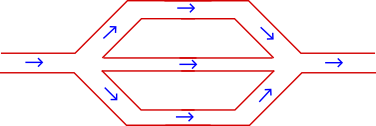
When the flow of the main pipe hits the fork, the flow will split according to some ratio into each of the branches. Finally when the branches re-combine in to a single flow it will be exactly the same as it was before the initial branching.
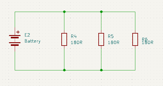
Here is a very simple demonstration.
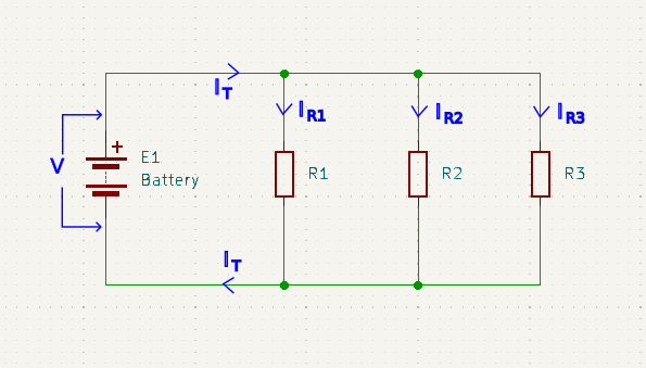
What we can immediately deduce from the above circuit is that:
- All the resistors must have the same voltage across them since they all connect to exactly the same two nodes.
- The total current is split up between each of the resistors.
- The current through each resistor, recombines with the current from all the other resistors to re-form the same total current that originally split up.
- The current through each resistor could be different.
Let’s see if we can derive an equation to calculate parallel resistance from that insight along with some simple Ohms law.
\(I_T = I_{R1} + I_{R2} + … + I_{Rn}\) then substituting V/R for I
\(\frac{V}{R_T} = \frac{V}{R_1} + \frac{V}{R_2} + … + \frac{V}{R_n}\) then dividing both sides by V
\(\frac{1}{R_T} = \frac{1}{R_1} + \frac{1}{R_2} + … + \frac{1}{R_n}\).
\(R_T = \frac{1}{\frac{1}{R_1} + \frac{1}{R_2} + … + \frac{1}{R_n}}\)
You may recognise 1/R as being the conductance equation. This makes perfect sense as each resistor path conducts a fraction of the total current.
Simplifications for Specialised Cases
There are a couple of shortcut simplified equations that can be used is some specialised circumstances:
N Resistors of Same Value in Parallel
In the case of any number of resistors, each with the same value, in parallel we get the following simplification of the equation – let n be the number of like resistors in parallel, and x be the value of each resistor then:
\(\frac{1}{R_T} = n \frac{1}{R_x} = \frac{n}{R_x}\) then taking the reciprocal of both sides
\(R_T = \frac{R_x}{n}\) where x is each resistor value and n is the number of resistors
Two Resistors in Parallel
In the case of there just being two resistors in parallel, then the equation simplifies as follows:
\(\frac{1}{R_T} = \frac{1}{R_1} + \frac{1}{R_2}\) multiplying top & bottom by the product of denominators
.
\(\frac{1}{R_T} = \frac{R_2 + R_1}{R_1.R_2}\) taking the reciprocal of both sides
.
\(R_T = \frac{R_1.R_2}{R_1 + R_2}\) but this only works for two resistors
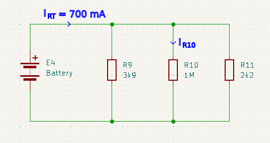
Current Divider Circuits
Let’s see if we can derive an equation for calculating the current in any of the parallel branches using only what we already know about calculating parallel resistance and what we know from Ohms law.
\(I_n = \frac{V_n}{R_n}\) but since all branches have the same V
\(I_n = \frac{V}{R_n}\) and we know from Ohms law that V=I.R so
\(I_n = \frac{I_T R_T}{R_n} = I_T \frac{R_T}{R_n}\) where RT/Rn is the ratio of current through this branch
Instinctively this equation may feel wrong, but what you have to remember is that RT is always smaller than the smallest Rn in the circuit.
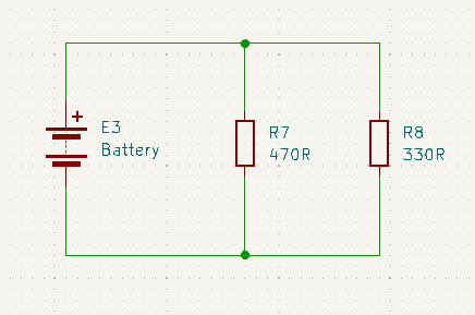
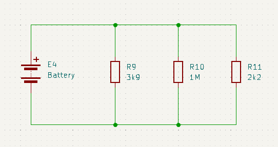
Now let’s try some examples for practice.