- What is electricity?
- Resistance, Conductance & Ohms Law
- Practical Resistors
- Power and Joules Law
- Maximum Power Transfer Theorem
- Series Resistors and Voltage Dividers
- Kirchhoff’s Voltage Law (KVL)
- Parallel Resistors and Current Dividers
- Kirchhoff’s Current Law (KCL)
- Δ to Y Network Conversion
- Y to Δ Network Conversion
- Voltage and Current Sources
- Thevenin’s Theorem
- Norton’s Theorem
- Millman’s Theorem
- Superposition Theorem
- Mesh Current Analysis
- Nodal Analysis
- Capacitance
- Series & Parallel Capacitors
- Practical Capacitors
- Inductors
- Series & Parallel Inductors
- Practical Inductors
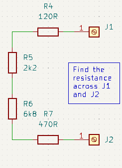
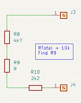
Series Resistor Circuits
Making further use of our analogy with water circuits. Resistors are like pipes and when you connect pipes together in series (end to end) they provide only a single path for the water. Hence they all carry exactly the same volume of flow. Thinner (higher resistance) pipes may have a higher pressure (voltage) and so faster flow. And fatter (lower resistance) pipes may have a lower pressure (voltage) and so slower flow, but the flow volume (I) is the same in all the pipes. Assuming that the pipe is full of water, then a litre flows in at exactly the same rate that it flows out the other end.

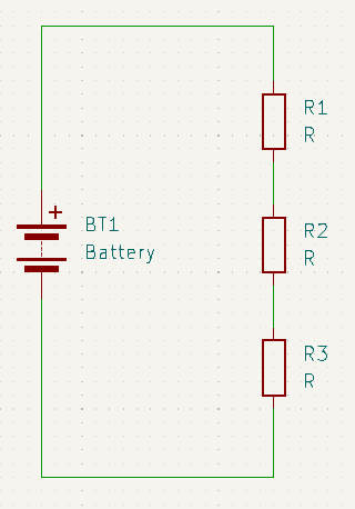
Similarly, series connected resistors provide only a single path for current to flow. Therefore all resistors in the path pass the same current. Also since there is only one path for current, it stands to reason that total voltage across all the resistors in series must be equal to the algebraic sum of the voltages across each individual resistor. From this we can derive an equation to calculate total resistance like so:
\(V_T = V_{R1} + V_{R2} + V_{R3}\) substituting IR for V
\(IR_T = IR_1 + IR_2 + IR_3\) dividing both sides by I
\(R_T = R_1 + R_2 + {…} + R_n\)
For series connected circuits, just add all the individual resistances together. In the example above we summed all three resistors to find the total resistance. However, the same procedure would also work to find the total resistance across the R1, R2 pair [RT = R1 + R2] (or R2, R3 pair [RT = R2 + R3]).
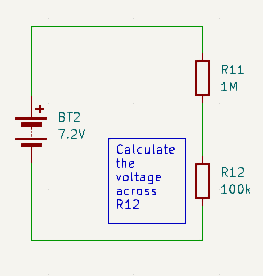
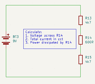
Voltage Divider Circuits
Since we know from ohms law that voltage is the product of current and resistance, and we know that the current through all the resistors in series is the same. We can deduce that the voltage across any given resistor is proportional to the total voltage across the whole series in the same proportion that it’s resistance has to the total resistance. In other words:
\(\frac{V_{Rn}}{V_{RT}} = \frac{R_n}{R_T}\) so…
\(V_{Rn} = V_T \frac{R_n}{R_T}\)
While on the face of things this may just seem like an interesting curiosity. It is such a fundamental structure that it is to be found in almost all practical electronic circuits. For example it is used to:
- Set bias values for transistors;
- Set the gain in amplifier circuits;
- Set up current limiting in certain transistor bias configurations;
- Set up proportional references that don’t change no matter what happens to the supply voltage;
- and many other places too.