- What is electricity?
- Resistance, Conductance & Ohms Law
- Practical Resistors
- Power and Joules Law
- Maximum Power Transfer Theorem
- Series Resistors and Voltage Dividers
- Kirchhoff’s Voltage Law (KVL)
- Parallel Resistors and Current Dividers
- Kirchhoff’s Current Law (KCL)
- Δ to Y Network Conversion
- Y to Δ Network Conversion
- Voltage and Current Sources
- Thevenin’s Theorem
- Norton’s Theorem
- Millman’s Theorem
- Superposition Theorem
- Mesh Current Analysis
- Nodal Analysis
- Capacitance
- Series & Parallel Capacitors
- Practical Capacitors
- Inductors
- Series & Parallel Inductors
- Practical Inductors
Maximum Power Transfer Theorem
This one of the simplest theorems that there are. It simply states that:
Maximum power will be transferred when the internal source resistance is equal to the load resistance.
This sounds counter intuitive to most people so some proof is often useful. However, the full proof requires the use of calculus which many find off-putting. So what I will present here is more of a visual demonstration, along with a light weight intuitive proof.
If you recall from our review of Power and Joules Law:
\(P = V.I\\\)and
\(V = I.R\\\)so substituting for V:
\(P = I^2.R\)
Since the output current from the source is the same as the input current to the load. It follows that they will both have the same power when they both have the same value for R. Just to demonstrate this in a more visual way I have prepared a Google Sheets chart of load resistance against power:
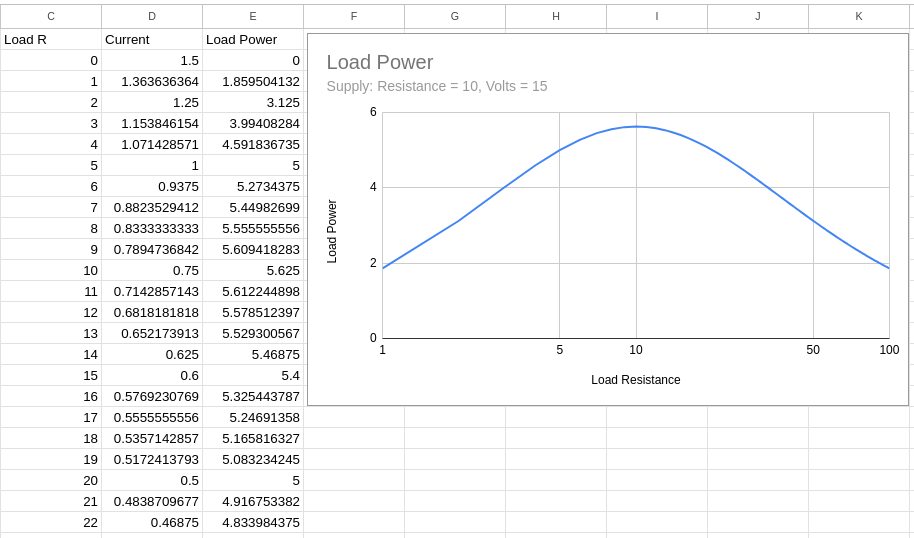
I have used a logarithmic scale for the ‘X’ axis as the power is related to the square of the current. Looking at the values for ‘I’ down column ‘D’ you can see that ‘I’ decreases steadily as ‘R’ decreases (in column ‘C’), but a strange thing happens to ‘P’ (in column ‘E’). At first it rises as ‘R’ rises up until ‘R’ reaches the source resistance value (10Ω in this case), when it starts to fall.
If you are still not convinced then try a few values for the source resistance and calculate a couple of values around that for the load resistance. It doesn’t matter what voltage you choose to use (I used 15V in the example, but feel free to try it with a value of 100V), that will only affect the peak power level, but not where it peaks.