- What is electricity?
- Resistance, Conductance & Ohms Law
- Practical Resistors
- Power and Joules Law
- Maximum Power Transfer Theorem
- Series Resistors and Voltage Dividers
- Kirchhoff’s Voltage Law (KVL)
- Parallel Resistors and Current Dividers
- Kirchhoff’s Current Law (KCL)
- Δ to Y Network Conversion
- Y to Δ Network Conversion
- Voltage and Current Sources
- Thevenin’s Theorem
- Norton’s Theorem
- Millman’s Theorem
- Superposition Theorem
- Mesh Current Analysis
- Nodal Analysis
- Capacitance
- Series & Parallel Capacitors
- Practical Capacitors
- Inductors
- Series & Parallel Inductors
- Practical Inductors
Norton’s Theorem
We have already looked at what a current source is in a previous article on Voltage and Current Sources. Norton’s theorem builds on that knowledge stating that:
Any linear electrical network containing only voltage sources, current sources and resistances can be replaced at terminals A–B by an equivalent combination of a current source IN in parallel with a resistance RN.
As a reminder here is a schematic for a practical current source equivalent circuit:
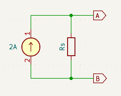
What Norton’s theorem is saying is that any circuit comprised of only current sources and resistors can be represented by the above equivalent circuit containing only a single current source and a single parallel connected resistor. The power of this revelation is that it can be used to simplify the analysis of circuits.
Norton in Action
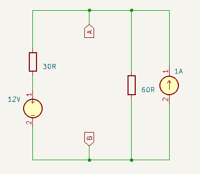
Consider the following, in which we will use RL to represent some arbitrarily complex target that we wish to analyse that is being powered by the surrounding circuitry:
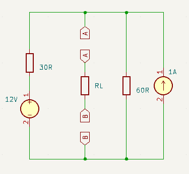
How much easier would it be to analyse the circuit represented by RL?
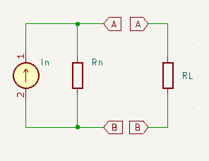
If the whole thing looked like this ➡
Deriving the Norton Equivalent
Step 1
Remove RL
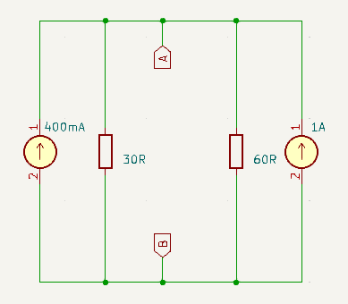
Step 2
Use the voltage-current source equivalency principle to derive the equivalent current source to replace the existing 12V, 30Ω voltage source:
\(I = \frac{V}{R} = \frac{12}{30} = 0.4A = 400mA\\\) \(R_{is} = R_{vs} = 30\Omega\)
Step 3
Short out terminals A and B, then calculate the Norton current (IN), by calculating the current that flows through the short:
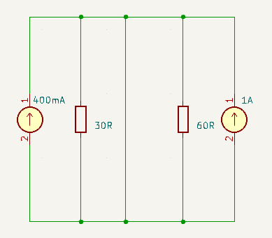
\(I_N = IS_1 + IS_2 = 400mA + 1A = 1400mA\)
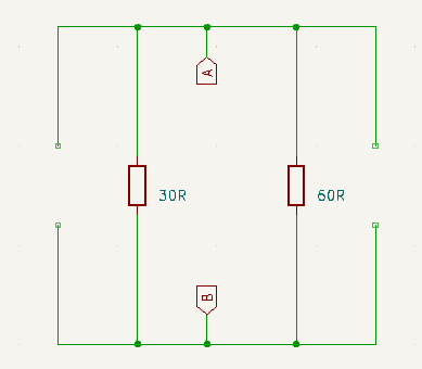
Step 4
Remove the short between A and B. Also remove all current sources leaving only their internal resistances:
Step 5
Calculate the Norton resistance (RN) by calculating the total resistance of the circuit:
\(R_N = \frac{R_1 . R_2}{R_1 + R_2} = \frac{30 * 60}{30 + 60} = \frac{1800}{90} = 20\Omega\)
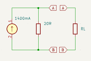
Step 6
Draw the Norton Equivalent Circuit: