- What is electricity?
- Resistance, Conductance & Ohms Law
- Practical Resistors
- Power and Joules Law
- Maximum Power Transfer Theorem
- Series Resistors and Voltage Dividers
- Kirchhoff’s Voltage Law (KVL)
- Parallel Resistors and Current Dividers
- Kirchhoff’s Current Law (KCL)
- Δ to Y Network Conversion
- Y to Δ Network Conversion
- Voltage and Current Sources
- Thevenin’s Theorem
- Norton’s Theorem
- Millman’s Theorem
- Superposition Theorem
- Mesh Current Analysis
- Nodal Analysis
- Capacitance
- Series & Parallel Capacitors
- Practical Capacitors
- Inductors
- Series & Parallel Inductors
- Practical Inductors
Practical Resistors
Materials
Resistors can be made from a wide variety of materials. Here are some examples of the most common types produced, along with a brief description of how they are made.
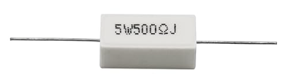
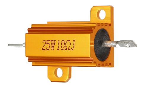
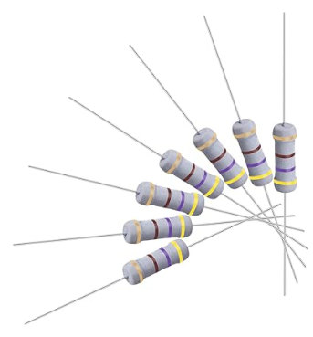
Wire Wound
Typically made by winding a resistive wire (such as nickle-chromium alloy) in a spiral around an insulating core (such as ceramic or fibreglass).
They are generally used where high power levels are being dissipated. The wire coil however, exhibits high levels of inductance and so they are not suitable for high frequencies.
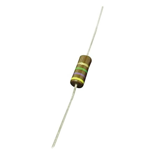
Carbon Composition
Made from a fine mixture of carbon and ceramic particles, compressed, then pressed in to a cylindrical shape and baked. The resistance depends upon the physical dimensions of the body along with the ratio of carbon to ceramic particles in the mixture.
Common in very old electronic circuits, but little used today because of its low tolerance (commonly 10%) and poor temperature coefficient.
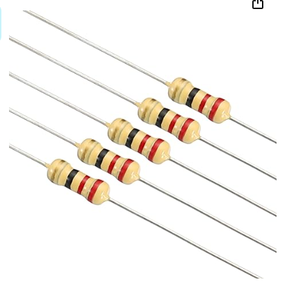
Carbon Film
Made by depositing a thin pure carbon film on an insulating (typically ceramic) core and then cutting a spiral on the surface to increase the resistive path.
Significantly more accurate (typically 5%) than the carbon composite type that they usurped. Quite common up to a decade or so ago, but now mostly superseded by metal film and metal oxide types.
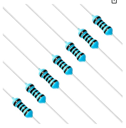
Metal Film
Typically made using either nichrome or tantalum nitride mixed with ceramic and deposited on an insulating flat or cylindrical core which then has a spiral groove cut out to set the resistance. Sometimes also referred to as cermet resistors due to the film composition.
Very common today due to better tolerances (typically 2%) and better temperature coefficients (typically 50 to 100 ppm/K). Though stability is lower than a wire wound, but without the high frequency issues.
Metal Oxide Film
Similar construction to metal film resistors, but uses an oxide, such as tin oxide, for the film.
They offer better reliability and stability than metal film resistors and offer a higher operating temperature. Though typically only 5% tolerance.
Still relatively expensive, so tend to be mostly used in applications where high endurance is important.
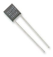
Foil
Constructed from a thin metal foil of several micrometers in thickness cemented on to a ceramic substrate.
Invented back in the 1960’s, they are still one of the most stable and accurate types today, though they are expensive. They feature a low temperature coefficient of resistance.
Used where high levels of precision are a necessity.
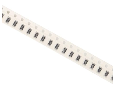
Thick Film
Constructed by printing a special paste on to an alumina ceramic substrate at a temperature of around 850℃. The paste is usually based on oxides of ruthenium, iridium and rhenium mixed with a binder and a carrier. The binder is a glassy frit and the carrier consists of organic solvent systems and plasticisers.
The paste is printed as pattern in layers on to the substrate as part of an additive process resulting in a final layer thickness of around 100µm.
The temperature coefficient is typically between 50 and 200 ppm/℃, with tolerances of between 1% and 5% available. Due to the low manufacturing costs these are the predominant SMD resistor type used today.
Thin Film
Constructed by the vacuum deposition of a metallic layer, often nichrome, to a depth of around 0.1µm, which around a thousandth of the thickness of thick film resistors. This layer is dense and uniform.
The actual desired resistance value is then achieved by either photo etching, or laser trimming a pattern in to the layer to increase the resistive path. Unlike thick film resistor manufacture, this is a subtractive process.
They tend to be used in precision applications as they are more expensive than thick film resistors, but offer tolerances between 0.1% and 2%, with a temperature coefficient of just 5 to 50 ppm/℃, along with relatively low noise.
Tolerances
As good as modern manufacturing techniques are. They are not perfect and the final value rolling off the end of the production line may not be precise and there will also be some slight variance between each resistor produced.
Since out of specification equates to manufacturing waste and ultimately extra cost, a process known as binning is used. This process assigns a range for allowable values to each bin. That is any resistor within some defined percentage of the target value is acceptable for that bin.
That is why resistors are sold as conforming within some specified tolerance of the specified value. For example, common tolerances are 5% and 1% (there are others too, but these are the most common).
Preferred Values
There is another potential issue for manufacturing costs, and that is the number of possible resistor values that would need to be produced to cover all scenarios (it would huge, arguably infinite).
To address the two issues of waste due to manufacturing tolerances and the sheer quantity of possible resistor values a series of standards have been created. These standards allow for a finite (and relatively small) range of values to be targeted for manufacture, while still covering all/most possible values.
Where more specific values are required, they can easily be created using series/parallel combinations of values from the range.
There are several of these standards which are sub-sets of each other. In which for a given standard, each value in a decade range is on the edge of the tolerance for the previous value in that decade. Each value specified is known as a preferred value.
Here is a table of the set of standards showing the tolerances for each standard and how many values that standard specifies for each decade range:
| Standard | Tolerance | # Values in a Decade | Preferred Values |
|---|---|---|---|
| E3 | 36% | 3 | 1, 2.2, 4.7 |
| E6 | 20% | 6 | 1, 1.5, 2.2, 3.3, 4.7, 6.8 |
| E12 | 10% | 12 | 1, 1.2, 1.5, 1.8, 2.2, 2.7, 3.3, 3.9, 4.7, 5.6, 6.8, 8.2 |
| E24 | 5% | 24 | 1, 1.1, 1.2, 1.3, 1.5, 1.6, 1.8, 2, 2.2, 2.4, 2.7, 3, 3.3, 3.6, 3.9, 4.3, 4.7, 5.1, 5.6, 6.2, 6.8, 7.5, 8.2, 9.1 |
| E48 | 2% | 48 | 1, 1.05, 1.1, 1.15, 1.21, 1.27, 1.33, 1.4, 1.47, 1.54, 1.62, 1.69, 1.78, 1.87, 1.96, 2.05, 2.15, 2.26, 237, 2.49, 2.61, 2.74, 2.87, 3.01, 3.16, 3.32, 3.48, 3.65, 3.83, 4.02, 4.22, 4.42, 4.64, 4.87, 5.11, 5.36, 5.62, 5.9, 6.19, 6.49, 6.81, 7.15, 7.5, 7.87, 8.25, 8.66, 9.09, 9.53 |
| E96 | 1% | 96 | E96 & E192 standards do exist, but they are rarely used. |
| E192 | 0.5% or better |
When designing electronic circuits, it is rare to need precise values for ‘R’. Rather than specifying, for example, 1.375kΩ. Ask yourself if you can get away with using one of the values from a preferred range. Start by seeing if a resistor from the E3 range could be used, if not how about from the E6 range etc.
The benefit as a hobbyist is two-fold: Firstly you don’t need to keep as many resistors in stock; Secondly, values exclusive to the higher standards are both rarer to find, and more costly.
Colour Codes
You may have noticed that many of the axial, through-hole resistors colour bands on them. These bands are used to let you know some important parameters for that resistor:
- It’s value.
- The tolerance to which the resistor has been manufactured.
- If there are 6 bands (very rare), then the temperature coefficient of the resistor
You should take the time to learn the value and tolerance colour codes as you will spend a lot of your time looking for resistors of the correct value.
| Colour | Value | Multiplier | Tolerance | Temperature coefficient |
|---|---|---|---|---|
| 0 | x 100 | N/A | N/A | |
| 1 | x 101 | ±1% | 100 ppm/℃ | |
| 2 | x 102 | ±2% | 50 ppm/℃ | |
| 3 | x 103 | ±3% | 15 ppm/℃ | |
| 4 | x 104 | ±4% | 25 ppm/℃ | |
| 5 | x 105 | ±0.5% | N/A | |
| 6 | x 106 | ±0.25% | 10 ppm/℃ | |
| 7 | x 107 | ±0.1% | 5 ppm/℃ | |
| 8 | x 108 | ±0.05% | N/A | |
| 9 | x 109 | N/A | N/A | |
| Gold | N/A | N/A | ±5% | N/A |
| Silver | N/A | N/A | ±10% | N/A |
There are three formats for the colour banding on through hole resistors:
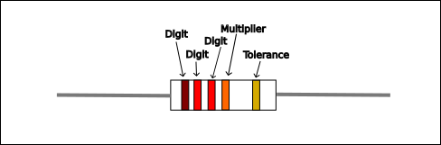
- 4 Band lines – 2 bands for the digits in the number, 1 band signifying what power of 10 to multiply the digits by, and 1 band denoting the tolerance, If the tolerance band is missing then the resistor has a 20% tolerance.
- 5 Band lines – same as the 4 band version, but 3 bands for the digits.
- 6 Band lines – Same as the 5 band version, with an added band denoting the temperature coefficient.
4 Colour Bands
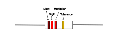
First two bands are the digits of the value (12 in this case) and the third band is the power of 10 multiplier (102 in this case) giving a value of 1200Ω (or 1.2kΩ usually written as 1k2 on schematic diagrams). The tolerance colour band is gold indicating a 5% tolerance for the value. This means that the value could be anywhere between 1140Ω and 1260Ω.
5 Colour Bands
First three bands are the digits of the value (122 in this case) and the third band is the power of 10 multiplier (103 in this case) giving a value of 122000Ω (or 122kΩ usually written as 122k on schematic diagrams).
The tolerance colour band is gold indicating a 5% tolerance for the value. This means that the value could be anywhere between 115900Ω and 128100Ω.
6 Colour Bands
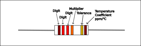
First three bands are the digits of the value (122 in this case) and the third band is the power of 10 multiplier (103 in this case) giving a value of 122000Ω (or 122kΩ usually written as 122k on schematic diagrams).
The tolerance colour band is gold indicating a 5% tolerance for the value. This means that the value could be anywhere between 115900Ω and 128100Ω.
The temperature coefficient band is brown indicating a coefficient of 100 ppm/℃. This means that for every 1MΩ, the value will change by 100Ω for every 1℃ change in temperature. Assuming that our resistor is actually the value marked (122kΩ), then in our case the value will change by:
\(100 * \frac{122000}{1000000} = 12.2\Omega/ ^{\circ}C\)
So for example if the resistor had a value of 122000Ω at 20℃, then at 30℃ the resistor would have a value of: 122000 + (10 * 12.2) = 122122Ω.
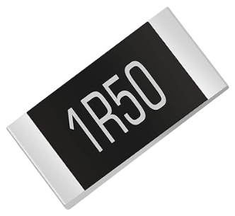
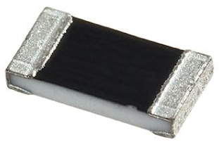
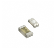
Surface Mount (SMD) Resistor Codes
Due to the small size of surface mount resistor devices colour codes are really practical. So a few different alpha-numeric code standards were created. The most common three being:
3 Digit Code
Very similar to the way that the resistor colour code works. The first two digits provide the number part of the value, and the third digit is the power of 10 that number must be multiplied by. So for example given the code “472” the value would be interpreted as 47 * 102 = 4700Ω or 4.7kΩ.
4 Digit Code
Works just like the 3 digit code, but the number is defined by the first three digits and the fourth digit is the power of 10 multiplier. So for example the code “1224” would indicate a value of 122 * 104 = 1220000Ω or 1.22MΩ.
EIA-96 System
This code is another 3 character code, but is based on the E96 preferred values standard and consists of two digits and a letter.
The two digits give a 1 based index in to the preferred values of the E96 range and the letter on the end indicates the multiplication factor. So to find the value you have to look it up in two different tables (or use one of the many online calculators).
| 100 | 102 | 105 | 107 | 110 | 113 | 115 | 118 | 121 | 124 | 127 | 130 | 133 | 137 | 140 | 143 |
| 147 | 150 | 154 | 158 | 162 | 165 | 169 | 174 | 178 | 182 | 187 | 191 | 196 | 200 | 205 | 210 |
| 215 | 221 | 226 | 232 | 237 | 243 | 249 | 255 | 261 | 267 | 274 | 280 | 287 | 294 | 301 | 309 |
| 316 | 324 | 332 | 340 | 348 | 357 | 365 | 374 | 383 | 392 | 402 | 412 | 422 | 432 | 442 | 453 |
| 464 | 475 | 487 | 499 | 511 | 523 | 536 | 549 | 562 | 576 | 590 | 604 | 619 | 634 | 649 | 665 |
| 681 | 698 | 715 | 732 | 750 | 768 | 787 | 806 | 825 | 845 | 866 | 887 | 909 | 931 | 953 | 976 |
| Code | Multiplier |
|---|---|
| Z | 0.001 |
| Y / R | 0.01 |
| X / S | 0.1 |
| A | 1 |
| B / H | 10 |
| C | 100 |
| D | 1000 |
| E | 10,000 |
| F | 100,000 |
So given a code of “04C” we would find the 4th entry in the E96 table (107 in our case), then lookup ‘C’ in the EIA-96 multiplier table (100 in our case) and then multiply them. So in our case we get 107 * 100 = 10700Ω or 10k7Ω.
Warning
Be aware that for resistors with a tolerance other than 1% (which E96 is specifically for) there are other tables of multiplier codes. However, not all manufacturers follow these stand codes so it is important to check the manufacturer notes to find what multiplier codes they are using.
Variable Resistors
So far we have only looked at the, admittedly wide variety of, fixed value resistors. However, there is another very important type of resistor who’s value can be adjusted (either by the end user, or at build time). These are available with either a linear or logarithmic progression. Some examples are:
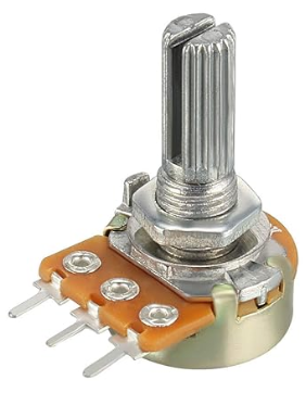
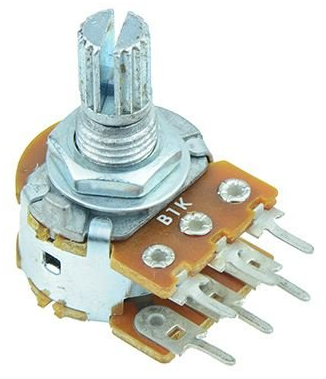
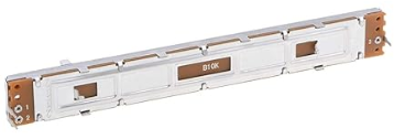
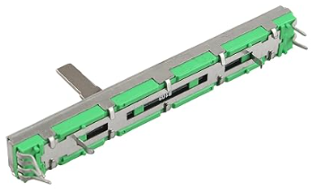
Potentiometer (Pot)
3 Terminal device mostly used to provide an adjustable voltage divider that an end-user can interact with. Typical example would be a volume control. Available as either a rotary or slider operation.
Also available in dual-gang form where two pots are controlled from a single knob/slider. Typical use would be on a stereo radio.
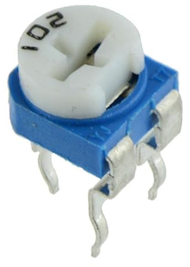
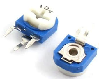
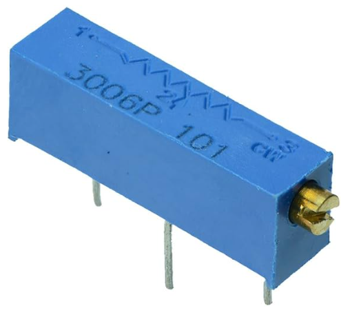
Trimmer/Preset Pot
3 Terminal device mostly used inside of appliances to allow service engineers to fine tune circuit operation. Like it’s bigger, user facing, counterpart it’s generally used as a variable voltage divider.
Available in both horizontal and vertical orientations. Also available as a multi-turn device for very fine tuning of values.
The vast majority of the time, these tiny devices require some kind of tool to adjust them.
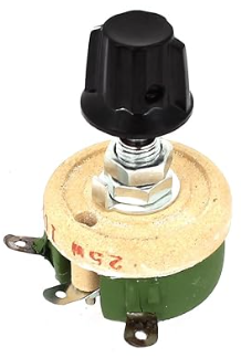
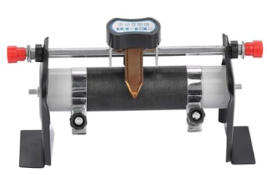
Rheostat
Usually a 2 terminal device (though a 3rd terminal may be provided to enable grounding of the device) and generally used to adjust the current in high voltage applications. Like the potentiometer it is often on a user facing interface.
Available in either rotary or slider operation.
Speciality Resistors
One final category of resistor are the speciality resistors. These are a type of variable resistor, but unlike those looked at so far which are adjusted by a human. These are operated automatically by some other kind of external changing condition. Some examples are:
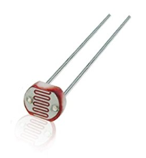
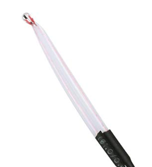
Light Dependent Resistor (LDR)
Also known as a photoresistor or photocell and typically based on a cadmium sulphide (CdS) cell. These are passive components who’s resistance drops as the light level increases. These are photo-conductors.
Though it varies considerably between devices, they typically have a resistance of a few kΩ in bright light, and > 1MΩ in complete darkness. They are also quite sensitive to temperature too, so they are not suitable for precision applications.
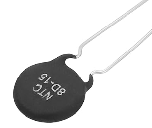
Thermister
A type of temperature dependent resistor which comes in two distinct flavours: Negative Temperature Coefficient (NTC) and Positive Temperature Coefficient (PTC).
With an NTC thermister, the resistance drops as the temperature rises. While with a PTC thermister, the resistance rises as the temperature rises.
Available in a variety of styles, they may be attached directly to a surface of interest, or mounted directly on to a printed circuit board (PCB).
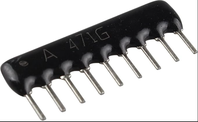
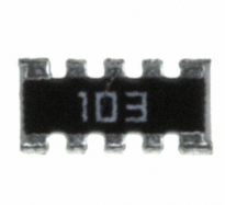
Resistor Network
Available in both Single In-Line (SIL) and Surface Mount (SMD) packaging. These devices contain arrays or configured networks of resistors. Commonly used for pull-up resistors on busses (usually packaged as 8 resistors of a single value, with one end being common).


Mechanical Feedback
These are not technically a different type of resistor, but rather a different way of using a variable resistor.
Most kinds of mechanical movement that are controlled by an electronic circuit utilise what is known as closed loop feedback. This is where a signal to move is applied to the device, and then the result of that movement is measured and fed back to the controlling circuit who’s control signal may change as a result of that feedback.
This type of system is seen everywhere from RC Servo motors to robotic arms. One of the ways that this feedback can be created is by mechanically linking a variable resistor to the moving part. As the part moves, so too does the potentiometer mechanism. Thus allowing an electrical feedback signal to be returned.