- What is electricity?
- Resistance, Conductance & Ohms Law
- Practical Resistors
- Power and Joules Law
- Maximum Power Transfer Theorem
- Series Resistors and Voltage Dividers
- Kirchhoff’s Voltage Law (KVL)
- Parallel Resistors and Current Dividers
- Kirchhoff’s Current Law (KCL)
- Δ to Y Network Conversion
- Y to Δ Network Conversion
- Voltage and Current Sources
- Thevenin’s Theorem
- Norton’s Theorem
- Millman’s Theorem
- Superposition Theorem
- Mesh Current Analysis
- Nodal Analysis
- Capacitance
- Series & Parallel Capacitors
- Practical Capacitors
- Inductors
- Series & Parallel Inductors
- Practical Inductors
Y to Δ (T to π) Network Conversion
Before reading this page I strongly suggest that you have first read and understood the complementary page on Δ to Y Network Conversion. The working out on this page is based on the results of that page.
Previously we looked at how to calculate the values for a ‘Y’ network to match an existing Delta (Δ) network. Now we will look at how to go the other way. Assuming there is an existing ‘Y’ network, this page looks at how to calculate appropriate values for an identical (electrically speaking) Delta network.
To re-cap here are schematics for each of the configurations, followed by the final equations for converting from Δ to ‘Y’ networks.
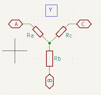
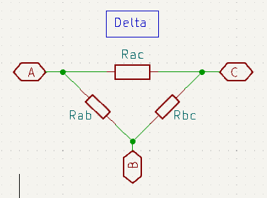
Equations for Delta (Δ) to ‘Y’ Conversion
\(R_a = \frac{R_{ab}R_{ac}}{R_{ab} + R_{ac} + R_{bc}}\\\) \(R_b = \frac{R_{ab}R_{bc}}{R_{ab} + R_{ac} + R_{bc}}\\\) \(R_c = \frac{R_{ac}R_{bc}}{R_{ab} + R_{ac} + R_{bc}}\)
Deriving ‘Y’ to Delta (Δ) Equations
What follows involves quite a lot of algebra. If you uncomfortable with how to transpose equations. I suggest that you first take a quick refresher here.
That all said, let’s dive right in…
First rearrange the Δ→Y equations to make their denominator the target:
\(R_a = \frac{R_{ab}R_{ac}}{R_{ab} + R_{ac} + R_{bc}}\) becomes \(R_{ab} + R_{ac} + R_{bc} = \frac{R_{ab}R_{ac}}{R_a}\\\)
\(R_b = \frac{R_{ab}R_{bc}}{R_{ab} + R_{ac} + R_{bc}}\) becomes \(R_{ab} + R_{ac} + R_{bc} = \frac{R_{ab}R_{bc}}{R_b}\\\)
\(R_c = \frac{R_{ac}R_{bc}}{R_{ab} + R_{ac} + R_{bc}}\) becomes \(R_{ab} + R_{ac} + R_{bc} = \frac{R_{ac}R_{bc}}{R_c}\\\)
so:
\(R_{ab} + R_{ac} + R_{bc} = \frac{R_{ab}R_{ac}}{R_a} = \frac{R_{ab}R_{bc}}{R_b} = \frac{R_{ac}R_{bc}}{R_c}\\\)
What we are really wanting to find is Rab, Rac, and Rbc in terms of Ra, Rb, and Rc. We’ll start off by finding Rbc.
\(\frac{R_{ab}R_{ac}}{R_a} = \frac{R_{ac}R_{bc}}{R_c}\\\) \(R_{ab} = \frac{R_{ac}R_{bc}}{R_c} \frac{R_a}{R_{ac}} = \frac{R_a R_{bc}}{R_c}\\\) \(\frac{R_{ab}R_{ac}}{R_a} = \frac{R_{ab}R_{bc}}{R_b}\\\) \(R_{ac} = \frac{R_{ab}R_{bc}}{R_b} \frac{R_a}{R_{ab}} = \frac{R_a R_{bc}}{R_b}\\\)Now substituting Rab and Rac from above in:
\(R_a = \frac{R_{ab} R_{ac}}{R_{ab} + R_{ac} + R_{bc}}\\\) \(R_a = \frac{\frac{R_a R_{bc}}{R_c} \frac{R_a R_{bc}}{R_b}}{\frac{R_a R_{bc}}{R_c} + \frac{R_a R_{bc}}{R_b} + R_{bc}} = \frac{\frac{R_a^2 R_{bc}^2}{R_b R_c}}{R_{bc} [\frac{R_a}{R_c} + \frac{R_a}{R_b} + 1]} = \frac{\frac{R_a^2 R_{bc}}{R_b R_c}}{\frac{R_a R_b + R_a R_c + R_b R_c}{R_b R_c}} = \frac{R_a ^2 R_{bc}}{R_a R_b + R_a R_c + R_b R_c}\\\)and transpose to make Rbc the target:
\(R_{bc} = \frac{R_a (R_a R_b + R_a R_c + R_b R_c)}{R_a^2}\\\) \(R_{bc} = \frac{R_a R_b + R_a R_c + R_b R_c}{R_a}\\\)
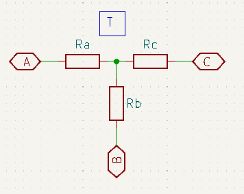
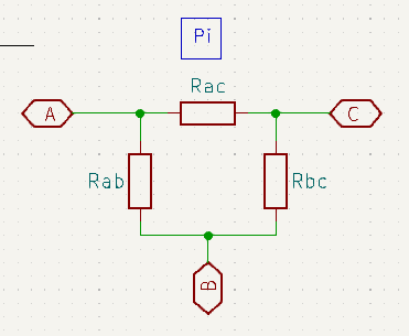
Well, that was a lot of algebra and finding Rab and Rac is just more of the same. So, I’ll leave the working up to you and just give a reminder of the schematics and the resulting three transformation equations below:
\(R_{ab} = \frac{R_a R_b + R_a R_c + R_b R_c}{R_c}\\\) \(R_{ac} = \frac{R_a R_b + R_a R_c + R_b R_c}{R_b}\\\) \(R_{bc} = \frac{R_a R_b + R_a R_c + R_b R_c}{R_a}\\\)
Aide-Mémoire
Clearly no-one in their right mind wants to go through all of that each time the conversion is required, and memorising yet another three (non-trivial) equations is not an appealing prospect. However, things are not a bad as they first appear.
It can be seen that the numerator is common across all three equations and is just the sum of products for each pair of resistors in the network. Meanwhile the appropriate denominator is found by looking which resistor (in the original circuit) is connected to the node opposite the new resistor that we wish to find the value for.