- What is electricity?
- Resistance, Conductance & Ohms Law
- Practical Resistors
- Power and Joules Law
- Maximum Power Transfer Theorem
- Series Resistors and Voltage Dividers
- Kirchhoff’s Voltage Law (KVL)
- Parallel Resistors and Current Dividers
- Kirchhoff’s Current Law (KCL)
- Δ to Y Network Conversion
- Y to Δ Network Conversion
- Voltage and Current Sources
- Thevenin’s Theorem
- Norton’s Theorem
- Millman’s Theorem
- Superposition Theorem
- Mesh Current Analysis
- Nodal Analysis
- Capacitance
- Series & Parallel Capacitors
- Practical Capacitors
- Inductors
- Series & Parallel Inductors
- Practical Inductors
The good news is that this law is just a very simple concept with no complicated equations to remember. Even if you never heard of Kirchhoff, you probably already know this law intuitively.
I tried really hard to think of a suitable analogy with water, but I came up short. Instead I will use the analogy of going for a circular walk in a hilly topology.

You park your car in the tourist car park and set off on your walk along the circuitous site seeing path. The journey follows many twists and turns and goes up and down many hills. Finally you arrive back at your car in the car park.
No matter how many hills you climbed on your journey, and no matter how many valleys you descended in to. At the end of your journey if you added up all the heights that you ascended and subtracted all the drops that you descended, you would end up with an answer of zero! This has to be true because you arrived back at exactly the same elevation as you set off from.
Kirchhoff’s Voltage Law
The algebraic sum of potential differences around any closed loop circuit is zero
An alternate phrasing of the law could be:
The sum of voltage gains is equal to the sum of voltage drops around any closed loop circuit
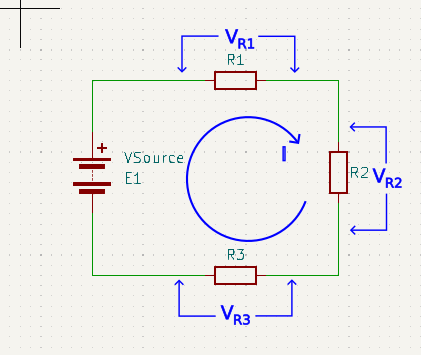
What this is saying, for the above shown circuit, is that the voltage across E1 is equal to all the voltage drops across R1, R2, and R3 added together. Something that is probably already blindingly obvious to you. Let’s put some real numbers in just to clarify what we mean.
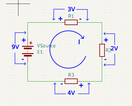
\(E_1 = V_{R1} + V_{R2} + V_{R3}\)
\(9V = 3V + 2V + 4V\)
\(9V – 3V – 2V – 4V = 0V\)
Notice that the polarities of the battery and the resistors are shown as opposite to each other. This is because the battery is a generator of voltage, but the resistors drop voltage.
We could have chosen to designate current flow as anti-clockwise and reversed all the polarity signs. The result would still have been the same.
To show that KVL works for all closed loops within a circuit, and not just in the simple case shown so far. Here is a slightly more complex circuit comprising two inner loops as well as an outer loop.
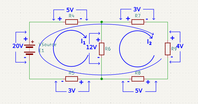
For the inner loop of I1 comprising the battery, R4, R6, and R5, assuming we choose to start at the junction between R5 and the battery:
20V – 5V – 12V – 3V = 0V
For the second inner loop of I2 comprising R9, R8, R6, and R7, assuming that we choose to start at the junction between R7 and R9:
-4V – 5V + 12V – 3V = 0V
Notice that VR9, VR8, VR7, are negative because their polarity is against the chosen current flow. Where as VR6 is positive because it’s polarity goes with the current flow.
Finally, for the final outer loop, we will arbitrarily choose to start at the junction between R8 and R5. To give a loop comprising R5, E1, R4, R7, R9, R8.
-3V + 20V – 5V – 3V – 4V – 5V = 0V
Notice that it doesn’t matter where you start the analysis, so long as you finish off where you start, and you observe the polarity dictated by the chosen direction of current flow.