- What is electricity?
- Resistance, Conductance & Ohms Law
- Practical Resistors
- Power and Joules Law
- Maximum Power Transfer Theorem
- Series Resistors and Voltage Dividers
- Kirchhoff’s Voltage Law (KVL)
- Parallel Resistors and Current Dividers
- Kirchhoff’s Current Law (KCL)
- Δ to Y Network Conversion
- Y to Δ Network Conversion
- Voltage and Current Sources
- Thevenin’s Theorem
- Norton’s Theorem
- Millman’s Theorem
- Superposition Theorem
- Mesh Current Analysis
- Nodal Analysis
- Capacitance
- Series & Parallel Capacitors
- Practical Capacitors
- Inductors
- Series & Parallel Inductors
- Practical Inductors
Voltage Sources
What is a voltage source? This may seem like a redundant question. After all, we know intuitively from our modern lives that voltage sources are plentiful and come in a variety of different forms… and they do. For example:
- Batteries or cells of various chemical technologies {Lead/Acid, NiCad, Alkaline, etc}
- Solar cells
- Mains outlet DC adaptors
- USB ports (in a variety of guises)
- Dynamos which are DC. As opposed to Generators which are AC and hence beyond the scope of this article.
- and so the list goes on.
All of the above are indeed sources of electricity, and hence voltage sources. However, from an electronics circuit analysis point of view an voltage source supplies a constant defined voltage, no matter what the load or power being consumed.
There are a couple of schematic symbols that are usually used to represent voltage sources in circuit diagrams:
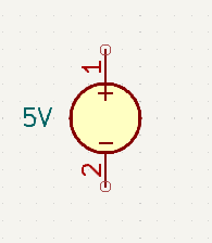
This is the most common symbol used to represent a generic DC voltage source. The positive terminal is denoted by the + sign, which in this example is towards the top of the symbol.
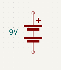
Usually used to indicate the DC voltage source for a circuit that is intended to be powered by a battery. The positive terminal is donated by the + sign. If the + sign is missing, then the positive end of each cell is designated by the longer plates, and the negative end by the shorter (and usually thicker) plates.
In practice however, such devices can’t exist as it would infer that they could supply an infinite amount of current, and that is not possible. So all real world voltage sources have some internal resistance which drops a little bit of voltage as current is drawn. Remember from Ohms law that V = I.R. Which means that as current draw increases, so too does the amount of voltage dropped across the internal resistance of the source.
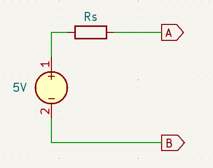
The real world equivalent circuit has a series connected resistor to represent the source resistance (to limit the output current). Here is an example shown using the generic voltage source symbol.
As an aside. Bench/Lab power supplies can appear to be ideal voltage sources while ever they are operating within their designed limits. However, they do in reality have an internal resistance. It is just that they work by supplying a fraction of the voltage that they themselves are supplied with. This let’s the internal voltage drop appear between the output and it’s own supply (while ever there is headroom), rather than between the output and the load.
Current Sources
What is a current source? This may be slightly less obvious than for voltage sources, but they are in fact very common within electronic circuits. A current source supplies a constant defined current no matter how the load on them changes.
Again these are a couple of the commonly used variations on the symbol used to represent current sources in schematic circuit diagrams:
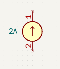
This is the most commonly used symbol used to represent a current source. The arrow is generally taken to point in the direction of conventional current flow.
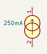
This variation seems to be used less these days, but is still seen often enough to warrant a mention here.
Once again, in the real world these idealised current sources can’t exist. Otherwise, since from Ohms law, V = I.R. When the circuit is not connected to anything, and the internal resistance was zero, there would have to be an infinite voltage at the output.
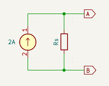
In practice current sources are modelled with a parallel shunt resistor. The purpose of the shunt being to limit the open circuit voltage of the device. Here is an example of a current source equivalent circuit:
As an aside. Bench/Lab power supplies can appear to be ideal current sources, but only within the defined set output limits. When using a bench power supply in constant current mode, it is also necessary to set a voltage limit which only applies if the load consumes less than the defined current. This is a very useful feature as it protects the load circuit from over-voltage damage.
Voltage & Current Source Equivalency
From the perspective of any load connected to either of the sources. The load doesn’t care what kind of source it is, so long as they both behave the same. So the question becomes; is it possible to design a practical constant current source to behave the same as a practical constant voltage source?
The short answer is yes. To see why, let us analyse the two circuits from extremes (ignoring actual values for the moment):
First Consider Terminals A and B to be Open Circuit
\(V_{AB} = V_s\\\)
\(I_{AB} = 0A\)
\(V_{AB} = I_s.R_s = V_s\\\)
\(I_{AB} = 0V\)
Now Consider Terminals A and B to be Short Circuited
\(V_{AB} = 0V\\\)
\(I_{AB} = \frac{V_s}{R_s} = I_s\)
\(V_{AB} = 0V\\\)
\(I_{AB} = I_s\)
Hence so long as Rs has the same value the circuits should look the same to the load.
So Now Find a value for Rs to match 5V and 2A and run the numbers.
\(R_s = \frac{Vs}{Is} = \frac{5V}{2A} = 2.5Ω\)
Open Circuit
\(V_{AB} = V_s = 5V\\\)
\(I_{AB} = 0V\\\)
Short Circuit
\(V_{AB} = 0V\\\)
\(I_{AB} = \frac{V_s}{R_s} = \frac{5V}{2.5Ω} = 2A\)
Open Circuit
\(V_{AB} = I_s.R_s = 2A.2.5Ω = 5V\\\)
\(I_{AB} = 0V\\\)
Short Circuit
\(V_{AB} = 0V\\\)
\(I_{AB} = I_s = 2A\)
Finally, run the numbers with with a load resistor of 1kΩ.
\(V_{AB} = V_s . \frac{R_s}{R_s + R_L} = 5 . \frac{1000}{2.5 + 1000} = 4.988V\\\)
\(I_{RL} = \frac{V_s}{R_s + R_L}\\\)
\(I_{RL} = \frac{5}{2.5 + 1000} = 0.004988A = 4.988mA\)
\(V_{AB} = I_s.\frac{R_s . R_L}{R_s + R_L} = 2 \frac{2.5 * 1000}{2.5 + 1000} = 4.988V\\\)
\(I_{RL} = I_s . \frac{Rs}{R_s . R_L}\\\)
\(I_{RL} = 2 \frac{2.5}{2.5 + 1000} = 0.004988A = 4.988mA\)
Identical results! So yes. The circuits are equivalent so long as Rs has the same value in both circuits. The usefulness of this is that it is sometimes more convenient to analyse a circuit using current rather than voltage, or vice versa.
Dependent Sources
Unlike the sources that we have looked at so far, which have a fixed output level that never changes (i.e. are independent of external influences). Dependent sources have an output level that is dependent upon (controlled by) some external influence (voltage or current source), which could be something as simple as the voltage across a thermister. There are four types of dependent sources:
- Voltage Controlled Voltage Sources (VCVS)
- Current Controlled Voltage Sources (CCVS)
- Voltage Controlled Current Sources (VCCS)
- Current Controlled Current Sources (CCCS)
The schematic symbols used for these sources are usually a diamond with either ‘+’ and ‘-‘ marked for a voltage source, or an arrow for a current source. The controlling input terminals may or may not be shown. What will be shown is the function that is applied to the controlling input to achieve the desired output.
Typically the function will often just be a scaling factor such as 10 or 0.5. It can however, be a non-linear function but we won’t cover that here. In either case the scaling function is applied to the controlling input value, and the result is what the output will be set to.
In the case of a voltage controlled source (of either kind), the control input port is theoretically an open circuit, but in practice is a high impedance. In the case of a current controlled source (of either kind), the control input port is theoretically a short circuit, but in practice a very low impedance.
Symbols
Here are some typical symbol representations:
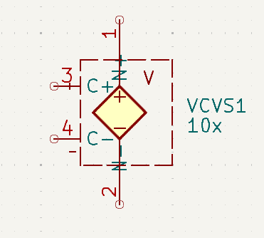
Voltage Controlled Voltage Source (VCVS)
The output voltage here will be 10x the control voltage.
If the control voltage is 300MV, then the output of the voltage will be 10 x 0.3V = 3V
A gain of 10 is shown here, but a gain of < 1 is also acceptable.
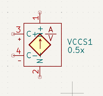
Voltage Controlled Current Source (VCCS)
The control value is amps per volt. So with the gain shown here of 0.5x and a control voltage of 400MV, the output current will be 0.5x 0.4 = 200MA.
A gain of < 1 is shown here, but gains > 1 are also acceptable.
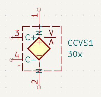
Current Controlled Voltage Source (CCVS)
The control value is volts per amp. So with the gain shown here of 30x and a control current of 150µA, the output voltage will be 30x 0.000150 = 4.5mV
A gain > 1 is shown here, but gains < 1 are also acceptable.
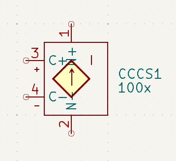
Current Controlled Current Source (CCCS)
The output current will be 100x the control current.
If the control current is 30µA, then the output current will be 100x 0.00003 = 3mA
A large gain is shown here, but gains of < 1 are also acceptable.