- What is electricity?
- Resistance, Conductance & Ohms Law
- Practical Resistors
- Power and Joules Law
- Maximum Power Transfer Theorem
- Series Resistors and Voltage Dividers
- Kirchhoff’s Voltage Law (KVL)
- Parallel Resistors and Current Dividers
- Kirchhoff’s Current Law (KCL)
- Δ to Y Network Conversion
- Y to Δ Network Conversion
- Voltage and Current Sources
- Thevenin’s Theorem
- Norton’s Theorem
- Millman’s Theorem
- Superposition Theorem
- Mesh Current Analysis
- Nodal Analysis
- Capacitance
- Series & Parallel Capacitors
- Practical Capacitors
- Inductors
- Series & Parallel Inductors
- Practical Inductors
Millman’s Theorem
Millman’s theorem says that:
when a circuit contains a parallel connected network of practical voltage sources (they MUST have a series internal resistance), they can be replaced by a single equivalent voltage source with a series resistance.
This theorem is not so much about performing circuit analysis directly, as it is about simplifying a circuit prior to performing some other circuit analysis technique. It is really just a consolidation of Ohms law with the voltage/current source equivalence theory. It works by summing the current from each of the voltages source branches and then multiplying that by the total resistance of those branches.
An alternative way of looking at the theorem is that it is just a Thevenin to Norton conversion, coupled with parallel resistance equations. Consequently, it is slightly more flexible than the opening statement, and many treatments of the theory would suggest.
It not only handles parallel voltage sources, as the theory states, but because of how it works it can also handle a mixture that includes current sources and just plain resistive branches too (with a slight variation on how the equation is populated).
Millman’s Equation
\(V_{out} = \frac{\frac{V_1}{R_1} + \frac{V_2}{R_2} + … + \frac{V_n}{R_n}}{\frac{1}{R_1} + \frac{1}{R_2} + … + \frac{1}{R_n}}\)
Which looks kind of unexpected at first because you were expecting to see a multiplication. However, remember that when you multiply two fractions together: The numerators get multiplied, then the denominators get multiplied. It just so happens in this case that the numerator of the second fraction is ‘1’ and the denominator of the first fraction is ‘1’. So you get this:
\(\frac{\frac{V_1}{R_1} + … + \frac{V_n}{R_n}}{1} . \frac{1}{\frac{1}{R_1} + … + \frac{1}{R_n}} = \frac{[\frac{V_1}{R_1} + … + \frac{V_n}{R_n}] * 1}{1 * [\frac{1}{R_1} + … + \frac{1}{R_n}]} = \frac{\frac{V_1}{R_1} + … + \frac{V_n}{R_n}}{\frac{1}{R_1} + … + \frac{1}{R_n}}\)
Example 1 – Just Voltage Sources in Parallel
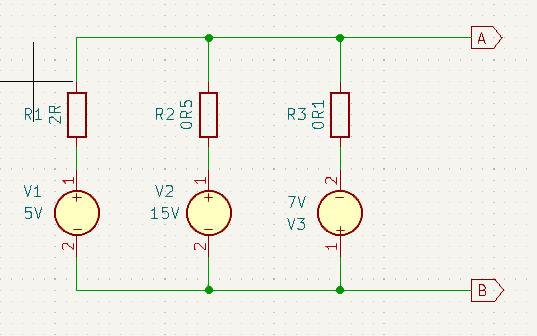
Here we have three voltage sources in parallel, each with it’s series internal resistance shown. To simplify analysing the circuit that this voltage network connects to, we want to simplify the voltage network down to just a single equivalent voltage source with series resistance.
Remember when we first looked at Ohms law and conductance. I said that there were times when it was more convenient to consider conductance rather than resistance. Well this is one of those times.
I find that I make less mistakes with the calculations if I split it down in to five stages:
- Calculate the sum of the currents generated
- Calculate the equivalent conductance of the network
- Calculate the equivalent voltage of the network
- Calculate the equivalent series resistance from the equivalent conductance
- Draw the equivalent circuit
Calculate the sum of the currents generated
\(I_{equivalent} = \frac{V_1}{R_1} + \frac{V_2}{R_2} + \frac{V_3}{R_3} = \frac{5}{2} + \frac{15}{0.5} + \frac{-7}{0.1} = -37.5A\\\)
Calculate the equivalent conductance
\(G_{equivalent} = \frac{1}{R_1} + \frac{1}{R_2} + \frac{1}{R-3} = \frac{1}{2} + \frac{1}{0.5} + \frac{1}{0.1} = 12.5S\\\)
Calculate the equivalent voltage
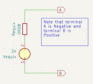
\(V_{equivalent} = \frac{I_{equivalent}}{G_{equivalent}} = \frac{-37.5}{12.5} = -3V\\\)
Calculate the equivalent resistance from the conductance
\(R_{equivalent} = \frac{1}{G_{equivalent}} = \frac{1}{12.5} = 0.08\Omega = 80m\Omega\)
Notice that V3 is reversed in the circuit with respect to the other voltage sources, so don’t forget the negative sign when inserting that voltage into the equations. Notice also, that as a result of the size of it’s negative voltage coupled with it’s correspondingly small internal resistance this voltage source contributes way more current than all the other sources. This explains the resulting equivalent voltage being negative. This just means that current from this voltage source network flows in the opposite direction to what we anticipated.
Here is the equivalent circuit schematic:
Example 2 – Mixture Voltage & Current Sources in Parallel
Here we have two voltage sources and a current source in parallel. Take note that the current source is in opposition to the two voltage sources. o simplify analysing the circuit that this voltage network connects to, we want to simplify the voltage network down to just a single equivalent voltage source with series resistance.
Once again I will use the same five stages from before to calculate the equivalent voltage source with just one minor adaptation to the equivalent current calculation. Since source number two is already a known current, we can insert that directly into the summation (being careful to observe polarity signs of course).
- Calculate the sum of the currents generated
- Calculate the equivalent conductance of the network
- Calculate the equivalent voltage of the network
- Calculate the equivalent series resistance from the equivalent conductance
- Draw the equivalent circuit
Calculate the sum of the currents generated
\(I_{equivalent} = \frac{V1}{R_1} + (-I2) + \frac{V_3}{R_3} = \frac{5}{2} + (-15) + \frac{3}{0.1} = 17.5A\\\)
Calculate the equivalent conductance
\(G_{equivalent} = \frac{1}{R_1} + \frac{1}{R_2} + \frac{1}{R_3} = \frac{1}{2} + \frac{1}{0.2} + \frac{1}{0.1} = 15.5S\\\)
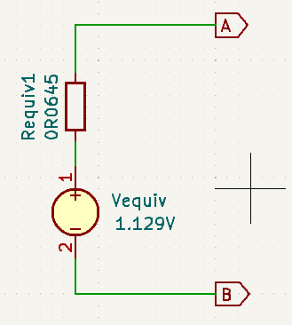
Calculate the equivalent voltage
\(V_{equivalent} = \frac{I_{equivalent}}{G_{equivalent}} = \frac{17.5}{15.5} = 1.129V\\\)
Calculate the equivalent resistance from the conductance
\(R_{equivalent} = \frac{1}{G_{equivalent}} = \frac{1}{15.5} = 0.0645\Omega = 64.5m\Omega\)
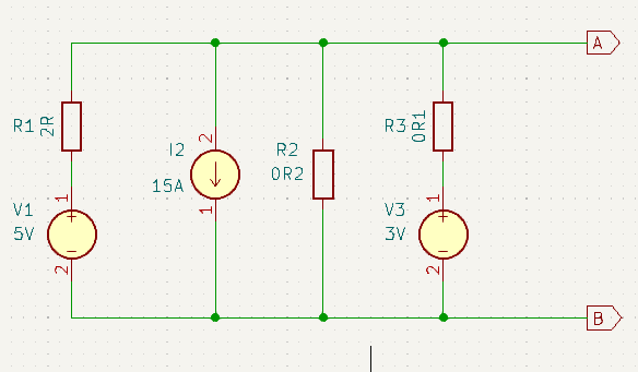
Example 3 – Mixture V & I Sources & Extra Parallel R’s
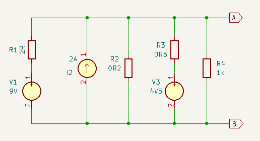
This time we have a mixture of not only voltage and current sources, but also with an extra parallel resistor in the mix. Once again the objective is to design an equivalent single voltage source with series resistor to replace this more complex circuit. At least this time all the sources have the same polarity.
- Calculate the sum of the currents generated
- Calculate the equivalent conductance of the network
- Calculate the equivalent voltage of the network
- Calculate the equivalent series resistance from the equivalent conductance
- Draw the equivalent circuit
Calculate the sum of the currents generated
\(I_{equivalent} = \frac{V1}{R_1} + I2 + \frac{V_3}{R_3} + 0 = \frac{9}{2} + 2 + \frac{4.5}{0.5} + 0 = 15.5A\\\)
Calculate the equivalent conductance
\(G_{equivalent} = \frac{1}{R_1} + \frac{1}{R_2} + \frac{1}{R_3} + \frac{1}{R_4} = \frac{1}{2} + \frac{1}{0.2} + \frac{1}{0.5} + \frac{1}{1000} = 7.501S\\\)
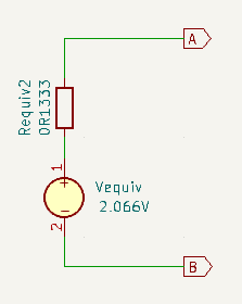
Calculate the equivalent voltage
\(V_{equivalent} = \frac{I_{equivalent}}{G_{equivalent}} = \frac{15.5}{7.501} = 2.066V\\\)
Calculate the equivalent resistance from the conductance
\(R_{equivalent} = \frac{1}{G_{equivalent}} = \frac{1}{7.501} = 0.1333\Omega \approx 133m\Omega\)