- What is electricity?
- Resistance, Conductance & Ohms Law
- Practical Resistors
- Power and Joules Law
- Maximum Power Transfer Theorem
- Series Resistors and Voltage Dividers
- Kirchhoff’s Voltage Law (KVL)
- Parallel Resistors and Current Dividers
- Kirchhoff’s Current Law (KCL)
- Δ to Y Network Conversion
- Y to Δ Network Conversion
- Voltage and Current Sources
- Thevenin’s Theorem
- Norton’s Theorem
- Millman’s Theorem
- Superposition Theorem
- Mesh Current Analysis
- Nodal Analysis
- Capacitance
- Series & Parallel Capacitors
- Practical Capacitors
- Inductors
- Series & Parallel Inductors
- Practical Inductors
Thevenin’s Theorem
We have already looked at what a voltage source is in a previous article on Voltage and Current Sources. Thevenin’s theorem builds on that knowledge stating that:
Any linear electrical network containing only voltage sources, current sources and resistances can be replaced at terminals A–B by an equivalent combination of a voltage source Vth in series with a resistance Rth.
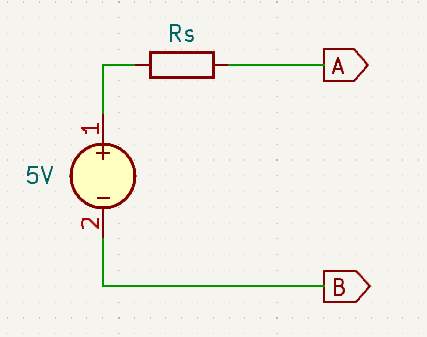
As a reminder. Here is a schematic for a practical voltage source equivalent circuit:
What Thevenin’s theorem is saying is that any circuit comprised of only voltage sources and resistors can be represented by the above equivalent circuit containing only a single voltage source and a single series resistor. The power of this revelation is that it can be used to simplify the analysis of circuits.
Thevenin in Action
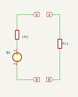
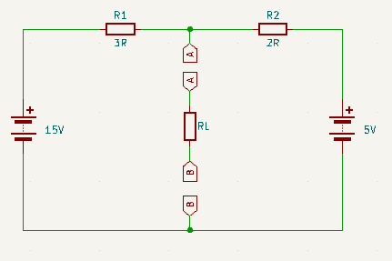
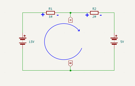
Consider the following, in which we will use RL to represent some arbitrarily complex target that we wish to analyse that is being powered by the surrounding circuitry:
How much easier would it be to analyse the circuit represented by RL?
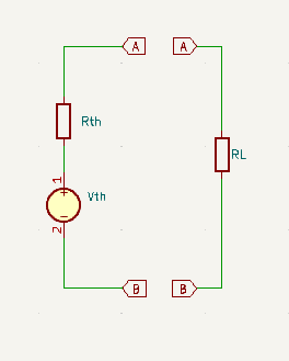
If the whole thing looked like this ➡
Deriving the Thevenin Equivalent
Step 1
Remove RL and choose arbitrary direction for current to be flowing around the remaining loop. By convention we will choose a clockwise direction.
Step 2
Use Kirchhoff’s Voltage Law to determine the voltage drop across the pair of resistors R1 + R2
\(15V – V_{R1} – V_{R2} – 5V = 0\\\)
\(15V – 5V = V_{R1} + V_{R2} = 10V\)
Step 3
Use series voltage divider theory to determine voltage drop across R1
\(V_{R1} = R1R2_{Drop} . \frac{R_1}{R_1 + R_2}\\\)
\(V_{R1} = 10 * \frac{3}{3 + 2} = 10 * \frac{3}{5} = 6V\)
Step 4
Calculate voltage across terminals A and B
\(V_{AB} = 15V – V_{R1} = 15V – 6V = 9V\)
Step 5
Calculate the equivalent resistance by replacing the voltage sources with a short circuit
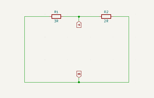
Step 6
Calculate the equivalent resistance across terminals A and B using parallel resistors equation
\(R_{AB} = \frac{R_1 . R_1}{R_1 + R_2} = \frac{3 * 2}{3 + 2} = \frac{6}{5} = 1.2\Omega\)
Step 7
Draw the Thevenin Equivalent Circuit